Timeline · (March 1961)
Flip-Flop Circuits
This article discusses the transistor circuits used in the Digital Computer Demonstrator shown in the photograph and on this month's cover. Manufactured by Aironics, Inc., 1035 E. 26th St., Hialeah, Florida, the unit is an educational aid for demonstrating how simple transistor circuits can perform basic computations.
THE digital computer, the electronic brain so widely used in industry and science, is an awesome giant. It's true that some computers—those housed in office-sized desks, for instance—are relatively small physically. But to the untrained eye, their internal workings are a veritable electronic nightmare. Of even more gargantuan concept are the mammoth versions which actually occupy the whole of specially designed, air-conditioned buildings.
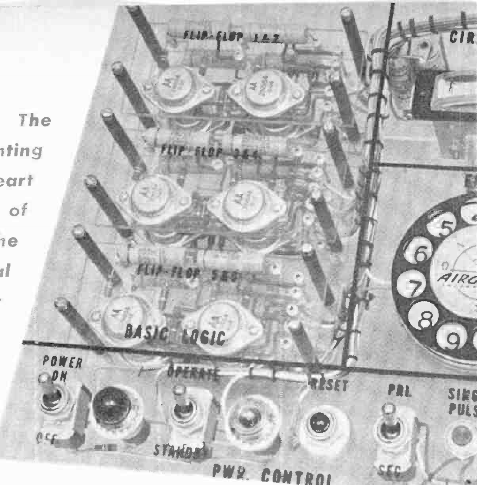
On closer inspection, however, the biggest digital computer proves to be only slightly more complex than a brick building. Made up of hundreds, sometimes thousands, of tiny printed-circuit boards—its "bricks," the digital computer also contains such rather unspectacular items as plug-in control panels, tape decks, and typewriter-like read-out machines. Interconnecting its multitude of components are precisely what you might think—miles and miles of wire!
One of the building "bricks" which make up the counting heart of the digital computer is the "flip-flop" circuit, usually tucked away within the computer on a printed-circuit board about the size of a postcard. One such "flip-flop" is the Eccles-Jordan bistable multivibrator. An easy way to visualize its operation is to think of it as an on-off toggle switch. Like the switch, a flip-flop must settle in one of two stable states. But unlike the switch, the "flipping" or "flopping" of the Eccles-Jordan is accomplished by electrical pulses quicker than the blink of an eye.
Before we actually set to work building one, let's take a closer look at the flip-flop and see how it is used. There's no quicker way to get on the road to computer understanding.
Flip-Flopping
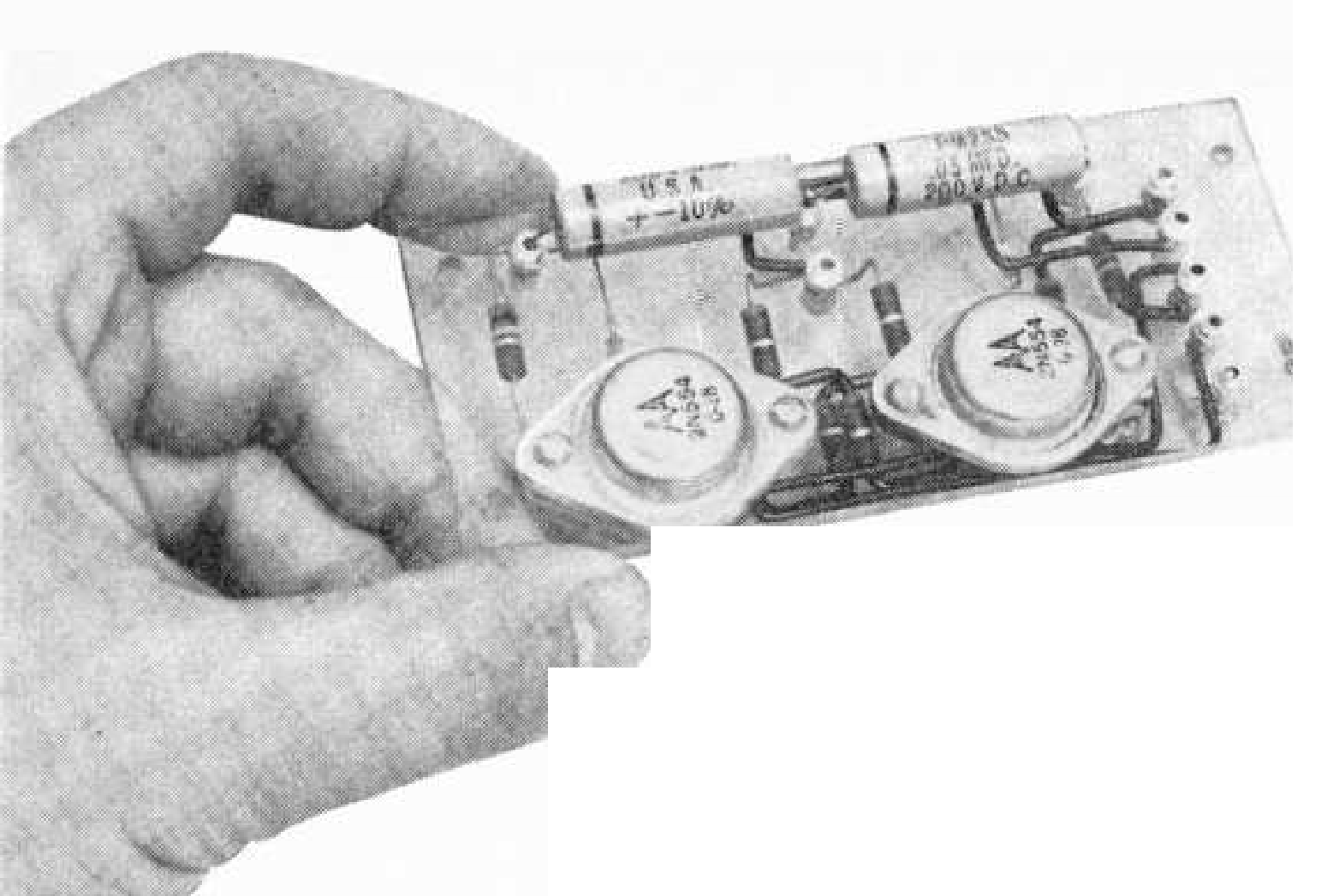
A typical flip-flop circuit using 2N554 p-n-p power transistors is shown in Fig. 1. Whenever power is applied to the circuit, one of the transistors will conduct and the other will be cut off. To understand how this happens, let's assume that transistor Q1 is conducting ("on") and transistor Q2 is cut off ("off"). The voltage at Q1's collector is low—less than one volt—due to the large collector current through R1.
The current through Q1 also passes through the common-emitter resistor, R4, developing a voltage drop which makes the top end of R4 more negative than its grounded end. The value of R4 is such that this would ordinarily make the base of Q1 more positive than the emitter (reverse bias), preventing Q1 from conducting. However, the base of Q1 receives enough negative voltage from the collector of Q2 to overcome this negative emitter voltage, keeping the base-emitter bias negative and transistor Q1 conducting.
The voltage at the collector of Q2 is approximately -7 volts (the same as the power supply voltage), since Q2 is not conducting and the voltage drop across R7 is almost zero. There is, however, a small current drain through R7 due to R6 and R3 and collector-emitter leakage in Q2.
Transistor Q2 is held at cutoff because the negative voltage at its emitter—due to the voltage drop across R4—is greater than the negative voltage reaching its base from the collector of Q1. In other words, the base of Q2 is positive compared to its emitter (reverse bias) and Q2 cannot conduct.
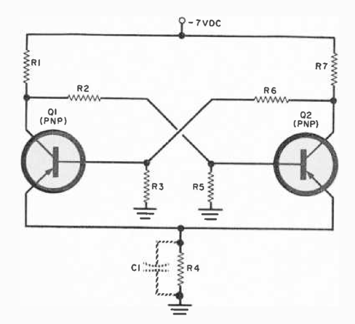
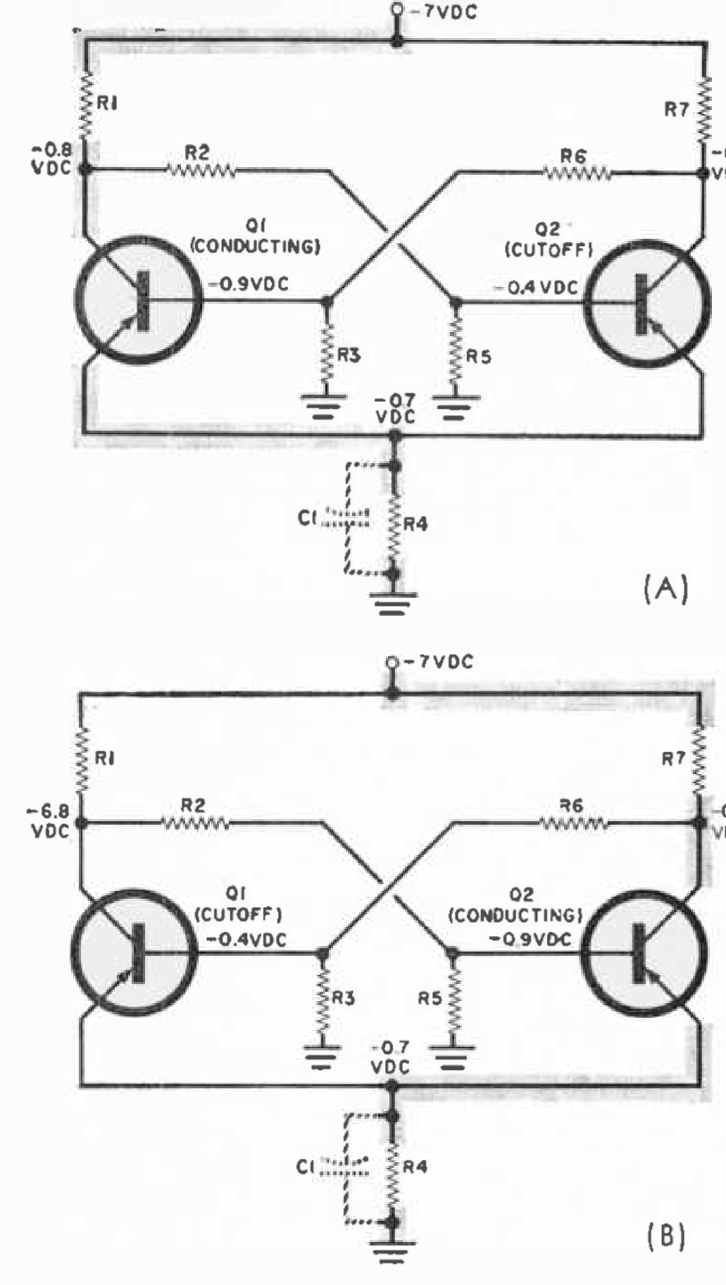
Figure 2 (A) shows the current path through the flip-flop multivibrator and d.c. voltages measured to ground when Q1 is conducting. The heavy lines show the current path from the -7 volt power supply, through Q1, to ground.
This state of affairs—Q1 "on" and Q2 "off"—will continue indefinitely because the flip-flop circuit is in a stable state. To reverse the transistor conditions—that is, to make the circuit "flip"—let's assume that we momentarily decrease the negative voltage on Q1's base so that the transistor stops conducting. The flip-flop now goes through a transition period of very short duration.
As Q1 cuts off, its collector voltage increases to -7 volts. The base of Q2, which was positive compared to its emitter, now becomes more negative, because the negative voltage at Q1's collector is passed on to Q2's base through a voltage divider, R2-R5. Transistor Q2 now conducts heavily and R7 drops the voltage at Q2's collector to less than a volt. This low negative voltage is transmitted through R6 and R3 to the base of Q1, permitting Q1 to remain in a cut-off state.
The circuit has now "flipped" and the transition period has ended. As before, the flip-flop is in a stable state, but Q2 is "on" and Q1 is "off." The multivibrator will remain in either stable state until a pulse from an external triggering circuit causes it to flip or flop. Figure 2 (B) shows the current path and circuit voltages when Q2 is conducting.
During the transition period, incidentally, when one transistor cuts off and the other is turned on, the voltage drop across R4 remains practically unchanged.
In many flip-flop circuit applications, R4 is bypassed by a high-value electrolytic capacitor, C1, to insure constant voltage on the emitters of Q1 and Q2 during the flip or flop of the multivibrator.
Triggering
Before we can put the flip-flop to work for us in a digital computer, some additions to the basic flip-flop circuit are necessary so that we can make either transistor conduct at will. The circuit shown in Fig. 3 is identical to that in Fig. 1 except that two input trigger signals can now be applied to the base of either transistor through capacitors C1 and C2.
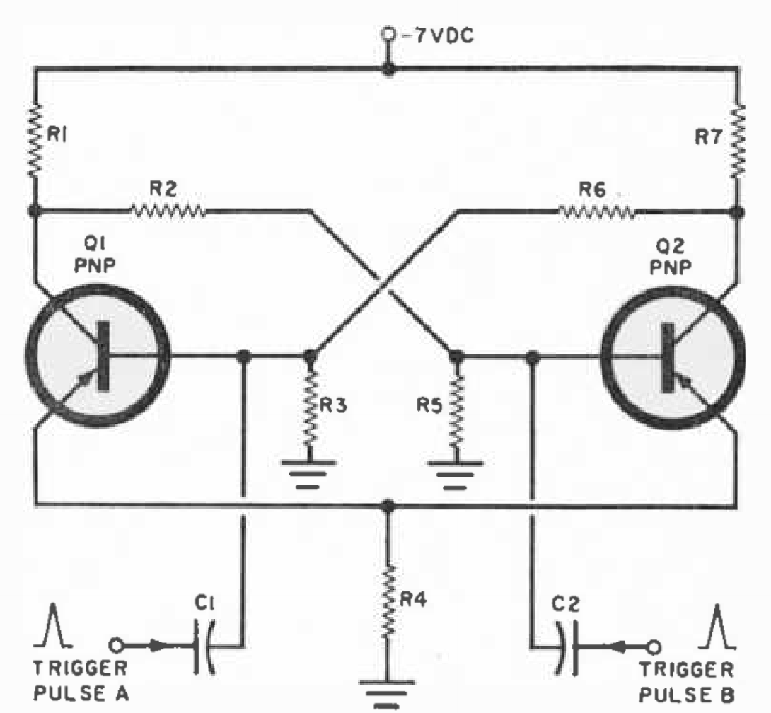
By applying a positive pulse to the base of the "on" transistor or a negative trigger pulse to the base of the "off" transistor, the circuit will switch from one state to the other. Let's consider the positive trigger pulse because we will see later that it can be obtained with a simple circuit using only a push-button switch and a resistor.
When Q1 is conducting (Fig. 3), a positive trigger pulse (A) is applied to the base of Q1. If this positive pulse is of sufficient amplitude, the base will be driven positive with respect to its collector and Q1 cut off. The collector voltage of Q1 will rise rapidly to -7 volts and a part of this voltage will be applied to the base of Q2 through voltage divider R2-R5. Transistor Q2 will now conduct, its collector voltage will drop to less than a volt, and this voltage will be applied to the base of Q1 via R6 and R3 to hold Q1 at cutoff when the positive trigger ends.
Obviously, we have just "flipped" the circuit. This same action takes place when a positive trigger pulse (B) is applied to Q2 as this transistor is conducting, although nothing will happen in the event that a positive pulse is applied to either transistor when it is not conducting. This results from the fact that when the transistor is cut off, a positive pulse only helps to keep it in its cut-off state. Therefore, no change will take place.
The flip-flop shown in Fig. 3 requires two trigger signals to "switch" it from one state to the other and back again. With the modified triggering circuit shown in Fig. 4, only one signal source is necessary.
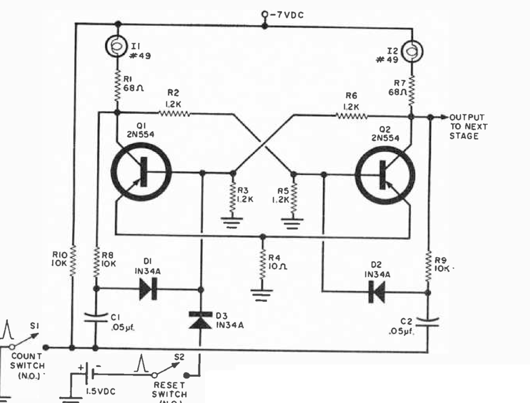
Let's see what happens in the circuit of Fig. 4 when Q2 is conducting. From Fig. 2 (B) we know that Q2's collector is more positive than its base. Diode D2, connected across the base and collector of Q2 through R9, is biased so that it will conduct heavily the instant a positive trigger pulse passes through C2. Diode D1 is wired in the same manner except that its anode is about six volts negative with respect to its cathode. Therefore, a positive trigger pulse must overcome this large negative bias before it can pass through D1.
Switch S1 controls the positive pulse that flips the circuit; note that the junctions of C1, C2, and S1 are connected to -7 volts through R10. When S1 is depressed, the -7 volts at this junction are quickly dropped to ground potential because one side of the switch is grounded. The sudden rise in voltage from -7 volts to zero is actually a positive pulse which is coupled through C2, and through conducting diode D2, to the base of Q2.
Although the same positive pulse passes through C1 to the anode of D1, it is not large enough to overcome the negative bias on the diode. When the positive pulse is applied to Q2's base, the circuit switches its conducting state and is ready for the next pulse. Now, a positive pulse will pass through diode D1 to the base of Q1 because the voltages seen by the diodes are reversed—refer back to Fig. 2 (A). The circuit will continue to flip and flop depending upon the number of positive pulses supplied to it.
Counting
The only things left unexplained about Fig. 4 are the two lamps and the reset circuit. The lamps indicate which transistor is conducting. When Q1 conducts, the large current passed by it must pass through I1. At the same time, I2 is not illuminated because Q2 is cut off. These lamps are useful in determining how many positive pulses are supplied by the count switch, S1.
Let's assume the count switch is depressed only once. Although one bulb will go out and the other will come on, we as yet have no way of determining which bulb will light—this will depend solely on which transistor was conducting before the button was depressed.
The reset switch, S2, is the answer to our problem. By depressing it before any count is made, we enable B1 to apply a positive voltage through D3 to the base of Q1, cutting off the transistor. Now, I1 is out and I2 is on, indicating a count of "zero." Although I2 should be in the circuit for balance, you can paint its glass so that it will show no light, since it is not used for counting.
With our flip-flop in operation, pressing S1 will turn I1 "on," indicating a count of "one." Pressing S1 a second time will return the lamp to the "off" state, indicating zero again. Although a single flip-flop such as this one can only indicate counts of zero and one by itself, other flip-flops can be added to the circuit and higher counts obtained. How this is done will be explained in the next issue of Popular Electronics. Binary counting will also be covered.
Build a Flip-Flop
In the meantime, so that you will fully understand how flip-flop circuits work, we suggest that you build the circuit shown in Fig. 4.
Measure the voltages at the terminals of the transistors and see how they agree with the theory discussed in this article. There may be slight voltage variations between the circuit you build and the values given in Figs. 2 (A) and 2 (B), but this is to be expected due to variations in tolerances of the components. Breadboard your circuit, keeping in mind that you will want to reuse the parts in circuits which will appear next month.
Figure 5 is the schematic diagram of a seven-volt power supply for the flip-flop. If you build it, wire it neatly—you will be using it again.
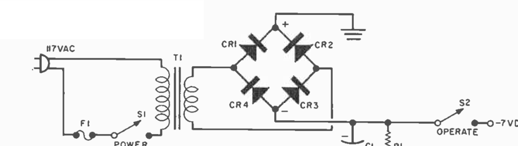
C1 — 1000-µf., 10-volt electrolytic capacitor
CR1, CR2, CR3, CR4 — 1N538 silicon diode (or equivalent)
F1 — 1-amp. fuse
R1 — 10,000-ohm, 1/2-watt resistor
S1, S2 — S.p.s.t. toggle switch
T1 — Filament transformer; 117-volt primary; 6.3-volt, 3-amp. secondary, CT not used (Knight 62G031 or equivalent)
Public domain reference document · Extracted from Popular Electronics, Vol. 14, No. 3, March 1961, pp. 59-62, 104.